F5, Inc. is an American technology company specializing in application security


Attackers are breaching F5 BIG-IP devices, check whether you've been hit -  Help Net Security 


F5, Inc. is an American technology company specializing in application security, multi-cloud management, online fraud prevention, application delivery networking (ADN), application availability & performance, network security, and access & authorization.
F5 is headquartered in Seattle, Washington in F5 Tower, with an additional 75 offices[3] in 43 countries[3] focusing on sales, support, development, manufacturing, and administrative jobs. Notable office locations include Spokane, Washington; New York, New York; Boulder, Colorado; London, England; San Jose, California; and San Francisco, California.
F5's originally offered application delivery controller (ADC) technology,but expanded into application layer, automation, multi-cloud, and security services. As ransomware, data leaks, DDoS, and other attacks on businesses of all sizes are arising, companies such as F5 have continued to reinvent themselves.[5] While the majority of F5's revenue continues to be attributed to their hardware products such as the BIG-IP iSeries systems, the company has begun to offer additional modules on their proprietary operating system, TMOS (Traffic Management Operating System.)  These modules are listed below and include, but are not limited to, Local Traffic Manager (LTM), Advanced Web Application Firewall (AWAF), DNS (previously named GTM), and Access Policy Manager (APM). These offer organizations running the BIG-IP the ability to deploy load balancing, Layer 7 application firewalls, single sign-on (for Azure AD, Active Directory, LDAP, and Okta), as well as enterprise-level VPNs. While the BIG-IP was traditionally a hardware product, F5 now offers it as a virtual machine, which they have branded as the BIG-IP Virtual Edition. The BIG-IP Virtual Edition is cloud agnostic and can be deployed on-premises in a public and/or hybrid cloud environmen

Getting started with Linux


 Getting started with Linux
 ============================
  UNIX -> Bell LAB (1969)- Dennis Ritchie
       -> Based on "C" Language

  UNIX Distribution:
  ------------------
=> IBM - AIX
  => HP - HPUX
=> SUN - SUN Solaris
=> UNIX-BSD

1969 - UNIX was Devloped, Ken Thompson and Dennis Ritchie
1971 - First edition of Unix released 11/03/1971.
1983 - AT&T is splitted -> It can sell software
1983 - The GNU project is first announced by Richard Stallman
1983 -

GNU (GNU Not UNIX) - 1983

A program is free software if the program's users have the four essential freedoms:
===================================================================================

=> The freedom to run the program as you wish, for any purpose (freedom 0).
=> The freedom to study how the program works, and change as you wish (freedom 1).
=> The freedom to redistribute copies so you can help your neighbor (freedom 2).
=> The freedom to distribute copies of your modified versions to others (freedom 3).

By doing this you can give the whole community a chance to benefit from your changes.

1986 - HP-UX 1.0 released.
1987 - Sun introduced
1987 - Minix Released
1991 - Linux is introduced by Linus Torvalds, a student in Finland.
Finland (Helsinki), 4th Year
1994 - Red Hat Linux is introduced.
1994 - Caldera, Inc was founded in 1994
2004 - The first release of Ubuntu is released October 20
2001 - Red Hat Enterprise Linux -

  Kernel:
  ------
  -> Hardware Management
  -> Process Management
  -> Driver Management
  -> Memory Mangement
 
 Linux Distribution:
 ------------------
  -> Red Hat (Commercial) ane Enterprise Support
  -> Fedora
  -> CentOS
  -> Ubuntu
  -> Debian
  -> Mint
  -> BackTrack
  -> Kali Linux
  -> Slackware
  -> Oracle Linux
  -> Open SUSE
  -> Mandrake
  -> Scientific Linux
  -> Open BSD
  -> Free BSD
  -> Android (Linux Kernel)

  Versoin:
  --------
   RHEL6.0
   RHEL6.1
   RHEL6.2
         .
    .
   RHEL 6.5
   RHEL 7.0(Current)
   RHEL 7.1(Current)

  OS Types:
  --------
      => Desktop
      => Server
      => IBM PowerPC
      => Super Computer
      => LiveOS

 OS Architecture:
 ----------------
  x86    (32 bit):i386, 2^32
  x86_64 (64 Bit):x64,  2^64

  Why Linux:
 ----------
 -> Security
 -> Free and Opensource
 -> 10x Times Faster Thand Windows
 -> Lighter
 -> Virusless
 -> Crash Less
 -> Low Hardware Requirements
 -> Multiuser System & Multitasking System

  RHCSA - Red Hat Certified System Administrator (300 Marks)
  RHCE - Red Hat Certified Engineer (300 Marks)
 
   => Pass mark: 210 for each part
   => Cost: $400 + $100(Original Book)
   => Total RHCE in Bangladesh: 1200+
   => Exam Types: Fully LAB based exam
   => Duration: 6.0 Hrs (Apporx.)
   => Authorized Partner in BD: IBCS, ITBangla, AT, Patshala, BASE
 
 Linux File System: ext2, ext3, ext4, xfs, birtFS, jfs
 Windows: NTFS, FAT32

 Drive Letter:
-------------
  Windows: C ..... Z
  Linux: SATA -> sdx1, sdx2 .............. sdx15 (x=a,b,c,d)
                 DVD -> sr0/dvd
USB -> sdx1 (x=a,b,c,d)
Floppy -> fd

 Requied Partition:
 -------------------
 Windows: C
 Recommanded: Linux: "/boot", "/", "swap"
=> / (root), Swap (virtual Memory)

 Filesytem Size:
 --------------
                /boot: 500MB
/    : as required (5G+)    
swap: 1G+ depends on RAM (max 64GB)

 Linux Installation:
 -------------------
        => Dual Boot: Linux + others  (Free Space: 8G)
=> Single Boot: Linux
=> Virtual BOx/VMware (Free Space: 8G)

 Installaiton Kits:
 ------------------
=> Dual Boot: DVD/USB/Network
        => Single BOot: DVD/USB/Network
=> Virtual Box: ISO/DVD/Network

 ================= The End ======================

 Course Plan:
 ------------
  RHCSA - System Administration
  RHCE - Network Administration

 System Administration
----------------------
 => user and group addministration
 => permission and ownership
 => disk managagement (lvm,iscsi,swap,raid)
 => process monitoring
 => scheduling
 => Packages management
 => network configuration
 => shell scripting
 => linux command line utilities
 => Linux Text processing tools
 => working with SElinux
 => PXE and kickstart
 => Virtualization with KVM

 Server/Network Administration:
-------------------------------
 => SSH application
 => NFS server
 => Web Server
 => proxy server (http and https and virutal hosting)
 => DNS server
 => Mail server (postfix+squirrelmail+webmail+outlook)
 => firewall
 => Monitoring (cacti/nagios)
 => Samba file server
 => iscsi server
 => database with MariadB

 ==================== X ====================

[Note: Tutorial made by  Md. Azaj Ikbal (CSL training) ]

Password Recovery Procedure for the Cisco Router

Password Recovery Procedure for the Cisco Router

Perform these steps in order to recover your password:

c2900-password-recovery-01.gif
  1. Switch on the router.
  2.   Press ctrl + pausebreak on the keyboard
  3. rommon 1>confreg 0x2142    ;in order to boot from Flash.
  4.  rommon 1> reset                ;The router reboots, but ignores the saved configuration.
  5. Router> enable                      ;You are in enable mode and should see the Router#
  6. Router# configure memory or copy startup-config running-config  ;in order to copy the nonvolatile RAM (NVRAM) into memory.
  7. warning Warning:  Do not enter copy running-config startup-config or write. These commands erase your startup configuration.
  8. Type enable secret 
    hostname(config)#enable secret cisco
  9. Type config-register
    hostname(config)#config-register 0x2102
  10. Type write memory  in order to commit the changes.

Resetting Password of Cisco Switch

Resetting Password of Cisco Switch  


1: Connect the console cable to your PC and router
2  Download Putty and Start a Serial Connection
3. Hold the mode button on the front of the  switch
4. Power on the switch
5. Once characters are displayed on the screen release the mode button
6. Press ctrl + pausebreak on the keyboard
7. Enter the following commands 
                                   Switch: flash_init 
                                   Switch:dir flash: 
                                   Switch:rename flash:config.text flash:config.backup 
                                   Switch:boot 
8. Rename Configuration files & Remove passwords

                                 Would you like to enter the inital configuration dialog? 
no 
                                 Switch > enable 
                                 Switch#renameflash:config.backup config.text 
                                 Switch#copy flash:config.text system:running-config 
                                 SW1#config terminal 
                                 SW1(config)#no enable secret. 
                                 SW1(config)#exit 

                                 SW1(config)#wr

Policy routing implementation example

Policy routing implementation example

Basically when you implement routing you have set of routes (static or dynamic) that tell the router how to reach certain destination. Policy routing does the same task, but may be different routes for various types of traffic. All routes by default are installed into main routing table which content can be displayed with following command:
[admin@MikroTik] /ip route> print where routing-mark=main
All routes with  appropriate routing-mark are shown using command:
[admin@MikroTik] /ip route> print
or
[admin@MikroTik] /ip route> print where routing-mark=all
In this case routing-mark denote appropriate routing table.
When we implement the policy routing there can be used others routing tables that includes routes for specific traffic or destination network. In this example, are explored the requirements for setting up policy routing and is given simple implementation example.
Implementation of policy routing consists of 3 steps:
  • The first step is to define the routes and which policies (routing table) will use those routes.
  • The second step to define the routing rules, which will define how the policies apply to certain traffic.
  • The third is to define the actual policies. We’ll look at each of these individually.
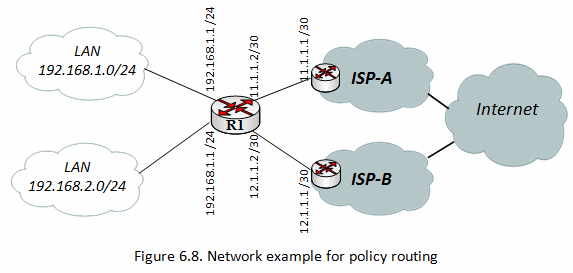
The network below is the one we will use for this example.
Imag6007.gif
Task of this example is to create routing policy that route all traffic from LAN 192.168.1.0/24 over provider “ISP-A” and all traffic from 192.168.2.0/24 via provider ISP-B.

Set up routing policy using ip route rule

I assume that IP addresses already have set up on your router. We will add three “default” routes for each of routing table. These are below:
/ip route add dst-address=0.0.0.0/0 gateway=11.1.1.1 routing-mark=Table_A 
/ip route add dst-address=0.0.0.0/0 gateway=12.1.1.1 routing-mark=Table_B 
/ip route add dst-address=0.0.0.0/0 gateway=11.1.1.1

The first two routes will be used by our policies, one for routing table Table_A and one for Table_B. The third route will be used by any traffic does not have a policy defined and by traffic from the router itself (it refered to main routing table), to define routing-mark=main is not mandatory because it is by default.

Next, we need to define our routing rules (policy). There are several ways to accomplish this, and one of simplest way is given below.
/ip route rule>add src-address=192.168.1.0/24 action=lookup table=Table_A
/ip route rule>add src-address=192.168.2.0/24 action=lookup table=Table_B

Note: If routes entries in specific routing table doesn’t satisfy particular traffic router looks for next hop (gateway) in the main routing table.

Reference: https://wiki.mikrotik.com/wiki/Testwiki/IP_routing


Install Nagios3.5 on ubuntu14.4 LTS

A.    Install Apache2
Install Apache2 to Configure HTTP Server. HTTP uses 80/TCP.
[1]          Install Apache2.
root@www:~# apt-get -y install apache2
[2]          Configure Apache2.
root@www:~# vi /etc/apache2/conf-enabled/security.conf
# line 26: change
ServerTokens Prod
        # line 37: change
          ServerSignature Off

root@www:~# vi /etc/apache2/mods-enabled/dir.conf
# line 2: add file name that it can access only with directory's name
DirectoryIndex index.html index.htm

root@www:~# vi /etc/apache2/apache2.conf
# line 70: add server name
ServerName www.srv.world

root@www:~# vi /etc/apache2/sites-enabled/000-default.conf
# line 11: change admin email address
ServerAdmin webmaster@srv.world

root@www:~# /etc/init.d/apache2 restart
 * Restarting web server apache2
...done.

[3]          Access to "http://(your server's hostname or IP address)/" with web browser. It's OK if following page is shown. (default page)


B.   Use PHP Scripts      
Configure Apache2 to use PHP scripts.
[1]          Install PHP.
root@www:~# apt-get -y install php5 php5-cgi libapache2-mod-php5 php5-common php-pear
[2]          Configure Apache2.
root@www:~# a2enconf php5-cgi.conf
Enabling conf php5-cgi.
To activate the new configuration, you need to run:
  service apache2 reload

root@www:~# vi /etc/php5/apache2/php.ini
# line 879: uncomment and add your timezone
date.timezone = "Asia/Tokyo"
root@www:~# /etc/init.d/apache2 restart
 * Restarting web server apache2
...done.

[3]          Create a PHP test page and access to it from any clients with web browser. It's OK if following page is shown.


root@www:~# vi /var/www/html/index.php
<html>
<body>
<div style="width: 100%; font-size: 40px; font-weight: bold; text-align:center;">
<?php
      print Date("Y/m/d");
?>
</div>
</body>
</html>


C.   Nagios : Install       
Install Nagios which is an enterprise open source monitoring system.
[1]Install and start Apache httpd, refer to here.
[2]Install PHP, refer to here.
[3]          Install Nagios.
Also Install basic plugins to monitor nagios server itself.

root@dlp:~# apt-get -y install nagios3 nagios-plugins-basic
[4]          Configure Nagios.
root@dlp:~# vi /etc/nagios3/nagios.cfg
# line 145: change
check_external_commands=1

root@dlp:~# vi /etc/nagios3/apache2.conf
# line 37: change access permission

Allow From localhost 10.0.0.0/24
# change admin password

root@dlp:~# htpasswd /etc/nagios3/htpasswd.users nagiosadmin

New password:     # set password

Re-type new password:
Updating password for user nagiosadmin
root@dlp:~# /etc/init.d/nagios3 restart

* Restarting nagios3 monitoring daemon nagios3
...done.
root@dlp:~# /etc/init.d/apache2 restart

* Restarting web server apache2
...done.
[5]          Access to the "http://(Nagios server's hostname or IP address)/nagios3/" from a client which is in the network allowed by Nagios server and authenticate with the Nagios admin user "nagiosadmin" to login.


[6]          After successing authentication, the Nagios admin site is displayed.


Nagios : Add Monitoring Target Host#1
               
It's possible to monitor other servers on the network.
[1]          For exmaple, add a server for monitoring target with simply Ping command.

root@dlp:~# vi /etc/nagios3/conf.d/node01.cfg
# create new

define host{
    use                     generic-host
    host_name               node01
    alias                   node01
    address                 10.0.0.51
}
define service{
    use                     generic-service
    host_name               node01
    service_description     PING
    check_command           check_ping!100.0,20%!500.0,60%
}

root@dlp:~# /etc/init.d/nagios3 restart

[2]          It's possible to view the status for a new server on the admin site.


Policy base Routing (2 WAN- 2LAN) in mikrotik router


Policy Based Routing (2 WAN- 2LAN) in mikrotik router 


We will assume that you already have the IP addresses set up on your router.
First, we must define our routes. We will add three “default” routes. These are below:
/ip route
add gateway=10.10.11.1 routing-mark=ISP2
add gateway=10.10.10.1 routing-mark=ISP1
add gateway=10.10.10.1 
add gateway=10.10.11.1  distance 10

All traffic from the 192.168.0.0/24 network will use ISP1 and all traffic from the 192.168.1.0/24 network will use ISP2. Here is the implementation:

/ip firewall mangle
add chain=prerouting src-address=192.168.0.0/24 dst-address=192.168.0.1 action=accept 

add chain=prerouting src-address=192.168.1.0/24 dst-address=192.168.1.1 action=accept 


add chain=prerouting src-address=192.168.0.0/24 action=mark-routing \
new-routing-mark=ISP1 passthrough=no

add chain=prerouting src-address=192.168.1.0/24 action=mark-routing \
new-routing-mark=ISP2 passthrough=no


/ip firewall nat 
add chain=src-nat outinterface=ISP1_WAN action=masqurate  
add chain=src-nat outinterface=ISP2_WAN action=masqurate  
add chain=src-nat WAN action=masqurate  


[Ref:https://www.youtube.com/watch?v=m6tYANGC9o0]
[Ref:http://blog.butchevans.com/2008/09/mikrotik-policy-routing-implementation-example/]


SNMP in Cisco Router or Switch

SNMP in Cisco Router or Switch


Router#configure terminal 
Enter configuration commands, one per line.  End with CNTL/Z. 
Router(config)#
Router(config)#snmp-server community public RO             ; read only 
Router(config)#snmp-server community private RW          ; read and Write only 

Configuring PPTP (VPDN) Server On A Cisco Router


Configuring PPTP (VPDN) Server On A  Cisco Router

If you need to allow VPN access to your network from the outside world then setting your Cisco router up to be a PPTP server is an easy way to do it.

Firstly we need to enable VPDN:

vpdn enable
!
vpdn-group 1
accept-dialin
protocol pptp
virtual template 254

Now we need to create the virtual template:

interface virtual-template 254
ip unnumbered fastethernet 0/0
peer default ip address pool pptp-pool
no keepalive
ppp encrypt mppe auto
ppp authentication ms-chap ms-chapv2

Once the Virtual template has been configured we need to create the IP address pool that will be assigned to the PPTP client:

ip local pool pptp-pool 192.168.0.50 192.168.0.60

We will now need to create the username and password that will allow the PPTP client to authenticate with the router:

username pptpuser password pptppassword

Finally we need to allow PPTP through any access-lists we may have on the incoming interface by appending the configuration below:

access-list 123 permit tcp any host 94.142.65.249 eq 1723
access-list 123 permit gre any any

IP sla In Cisco router

Configuring a Basic ICMP Echo Operation 

Router cisco 1800

SUMMARY STEPS
    1.    enable 
    2.    configure terminal 
    3.    ip sla operation-number 
    4.    icmp-echo {destination-ip-address | destination-hostname} [source-ip {ip-address | hostname} |source-interface interface-name
    5.    frequency seconds 
    6.    end

    Example
ip sla responder

ip sla 10
 icmp-echo 192.168.1.1 source-interface GigabitEthernet0/5
 threshold 100
 timeout 1000
 frequency 3

ip sla schedule 10 life forever start-time now

ip sla 20
 icmp-echo 192.168.2.1 source-interface GigabitEthernet0/4
 threshold 100
 timeout 1000
 frequency 3

ip sla schedule 20 life forever start-time now


track 10 ip sla 10 reachability
 delay down 1 up 1
!
track 20 ip sla 20 reachability
 delay down 1 up 1


ip route 10.0.1.0 255.255.255.0 192.168.1.1 name PRI track 10
ip route 10.0.1.0 255.255.255.0 192.168.2.1 2 name RDN track 20

-----------------------------------------------------------------
                                                                   
                                                                     Router cisco 3800
SUMMARY STEPS

1. enable

2. configure terminal

3. ip sla monitor operation-number

4. type echo protocol ipIcmpEcho {destination-ip-address | destination-hostname} [source-ipaddr {ip-address | hostname} | source-interface interface-name]

5. frequency seconds

6. exit

7. ip sla monitor schedule operation-number [life {forever | seconds}] [start-time {hh:mm[:ss] [month day | day month] | pending | now | after hh:mm:ss] [ageout seconds] [recurring]

8. exit
9. track object-number rtr operation-number { statereachability }

Example

The following example shows the configuration of the IP SLAs ICMP Echo operation number 6 that will start immediately and run indefinitely.

 ip sla monitor 10
       type echo protocol ipIcmpEcho 172.29.139.134 source-ipaddr 172.29.139.132
       threshold 100
       timeout 1000
       frequency 3
 !
 ip sla monitor schedule 6 life forever start-time now

 track 10 rtr  10 reachability

 delay down 1 up 1

 ip sla monitor 20
       type echo protocol ipIcmpEcho 172.29.139.134 source-ipaddr 172.29.139.1
       threshold 100
       timeout 1000
       frequency 3
 !
 ip sla monitor schedule 6 life forever start-time now

 track 20 rtr  20 reachability

 delay down 1 up 1